Introduction
Verilog is a hardware description language (HDL) widely used for designing and verifying digital circuits. While designing a digital system, it is crucial to ensure that it functions correctly under various conditions. This is where testbenches come into play. A testbench is a critical component of the verification process, allowing you to simulate and test your Verilog designs before they are implemented in hardware. In this blog, we will explore the basics of creating a testbench in Verilog.
What is a Testbench?
A testbench is a separate Verilog code that acts as an environment for testing your design. It provides stimulus to your design and monitors its responses. The primary purposes of a testbench are:
- Stimulus Generation: The testbench generates input signals or stimuli to apply to your design under test (DUT).
- Monitoring and Checking: It monitors the DUT’s output and checks whether the results match the expected behavior.
- Debugging: Testbenches help identify and isolate issues in your design.
Components of a Testbench
A Verilog testbench consists of the following components:
- Module Instantiation: Instantiate the DUT within the testbench. This allows you to connect signals between the testbench and the DUT.
- Stimulus Generation: Create Verilog code to generate input signals to stimulate the DUT. You can use procedural blocks like
initialandalwaysfor this purpose. - Monitoring and Checking: Use procedural blocks to monitor the DUT’s output and compare it with expected values. You can use assertions or conditional statements for checking.
- Clock Generation: If your design relies on a clock signal, generate the clock waveform in the testbench.
- Testbench Inputs: Define inputs for the testbench that allow you to configure the test cases and parameters.
- Testbench Outputs: Create outputs in the testbench for reporting test results and debugging information.
Creating a Simple Verilog Testbench
Let’s walk through the process of creating a simple Verilog testbench for a hypothetical 2-to-1 multiplexer (MUX) as an example.
// 2-to-1 MUX module
module mux2to1 (input a, b, sel, output y);
assign y = (sel) ? b : a;
endmodule
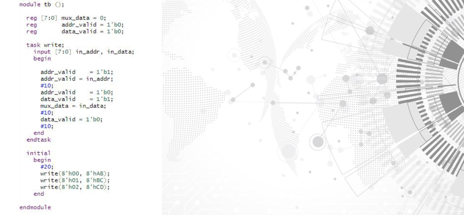
// Testbench for the 2-to-1 MUX
module tb_mux2to1;
// Inputs
reg a, b, sel;
// Output
wire y;

// Instantiate the MUX module
mux2to1 uut (
    .a(a),
    .b(b),
    .sel(sel),
    .y(y)
);

// Stimulus Generation
initial begin
    a = 0;
    b = 1;
    sel = 0;

    // Apply Test Case 1
    #10 sel = 1;
    #10 sel = 0;

    // Apply Test Case 2
    #10 a = 1;
    #10 sel = 1;
    #10 sel = 0;

    // Add more test cases here

    // Finish simulation
    $finish;
end

// Monitoring and Checking
always @(posedge y) begin
    // Check the output 'y' and report the result
    if (y === 0) begin
        $display("Test Passed");
    end else begin
        $display("Test Failed");
    end
end
endmodule
In this example:
- We have a 2-to-1 MUX module and a testbench module named
tb_mux2to1. - The testbench generates stimulus by toggling inputs
a,b, andseland monitors the outputy. - We use the
$displaysystem task to report test results. - The
alwaysblock monitors the rising edge of the output signalyand checks if it matches the expected behavior.
Running the Simulation
To run the simulation, you would typically use a simulator like ModelSim or XSIM (for Xilinx FPGA designs). The exact procedure may vary depending on the simulator you’re using, but generally, you would compile both the design and the testbench files and then simulate the testbench.
if you’re aspiring to master design verification in the field of VLSI, SuccessBridge stands out as the premier choice for training and education. With their top-notch VLSI training programs, you can gain the knowledge and hands-on experience needed to excel in design verification and make a significant impact in the world of digital design. Don’t miss the opportunity to join SuccessBridger, where your path to success in VLSI design verification begins.
Conclusion
Testbenches play a crucial role in verifying the correctness of your Verilog designs. They help ensure that your digital circuits behave as expected under various conditions. By following the basic principles of creating a testbench, you can effectively verify your designs and catch potential issues early in the design process. As you gain more experience, you can create more complex testbenches with a broader range of test cases to thoroughly validate your designs.