Introduction
System Verilog is a hardware description language (HDL) widely used for digital design and verification. It offers a rich set of features and constructs to model complex digital systems effectively. Two fundamental concepts in SystemVerilog that play a crucial role in design abstraction and organization are modules and interfaces. In this blog post, we’ll delve into these concepts to understand their significance in SystemVerilog design.
Modules: The Building Blocks
Modules are at the core of System Verilog design. They are analogous to functions or procedures in traditional programming languages but designed for hardware description. Modules encapsulate the functionality of a particular block or component of your design. They serve as the building blocks of your digital system, allowing you to create hierarchical and reusable designs.
Module Syntax
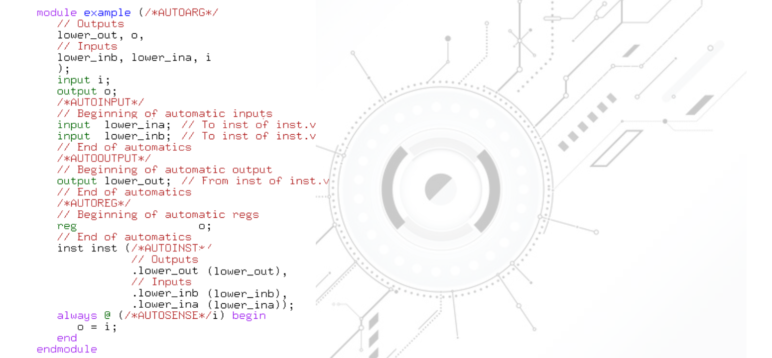
A System Verilog module consists of the following key elements:
- Module Keyword: A module is defined using the
modulekeyword, followed by the module’s name. - Port Declarations: Ports are the interface points through which modules communicate with each other. Ports can be inputs, outputs, or bidirectional. You declare ports within parentheses after the module name.
- Internal Declarations: Inside the module, you can declare and define internal signals, registers, and logic that constitute the module’s functionality.
- Behavioral Logic: The actual behavior of the module is described in its body using procedural and continuous assignment statements. You can use behavioral constructs like
always,if-else, and more to define the logic.
Hierarchical Design
One of the significant advantages of modules is hierarchical design. You can instantiate one module within another, creating a hierarchical structure that models your entire system. This modular approach promotes code reuse and simplifies complex designs by breaking them down into manageable blocks.
Interfaces: Streamlined Communication
Interfaces provide a structured way to define a group of signals that can be conveniently used to connect different modules. They act as a protocol for communication between modules, making it easier to integrate and verify designs with multiple interacting components.
Interface Syntax
To create an interface in SystemVerilog, you use the interface keyword, followed by the interface’s name. Inside the interface, you can declare various modport declarations, each specifying a subset of the interface signals for different purposes (e.g., data transfer, control, etc.).
Simplified Communication
Interfaces abstract away the low-level details of signal connections, making it easier to connect modules without worrying about individual signals. This simplification streamlines the integration process and reduces the chances of errors.
Example Use Case
Let’s illustrate the use of modules and interfaces with a simple example: a UART (Universal Asynchronous Receiver-Transmitter) communication module. In this case, you can create modules for the transmitter and receiver, each with their respective interfaces for data and control signals. These modules can then be instantiated and connected at the top-level module to create a complete UART communication system.
systemverilogCopy code
module UART_Transmitter #(parameter DATA_WIDTH = 8) ( input logic clk, input logic rst, output interface UART_TX_IF tx ); // Transmitter logic here endmodule module UART_Receiver #(parameter DATA_WIDTH = 8) ( input logic clk, input logic rst, input interface UART_RX_IF rx ); // Receiver logic here endmodule module Top_Module; UART_TX_IF transmitter_if (); UART_RX_IF receiver_if (); UART_Transmitter #(.DATA_WIDTH(8)) tx ( .clk(clk), .rst(rst), .tx(transmitter_if) ); UART_Receiver #(.DATA_WIDTH(8)) rx ( .clk(clk), .rst(rst), .rx(receiver_if) ); endmodule
Conclusion
Modules and interfaces are fundamental constructs in SystemVerilog that enable efficient hierarchical design and streamlined communication between modules. By using these concepts effectively, you can create modular and maintainable digital designs, which are crucial in the world of FPGA and ASIC design. Understanding and mastering these constructs is essential for any SystemVerilog designer or verification engineer.
if you’re aspiring to master design verification in the field of VLSI, SuccessBridge stands out as the premier choice for training and education. With their top-notch VLSI training programs, you can gain the knowledge and hands-on experience needed to excel in design verification and make a significant impact in the world of digital design. Don’t miss the opportunity to join SuccessBridge, where your path to success in VLSI design verification begins.